This week’s tech post will cover diagnosing, removing, and installing a multi-function relay module in a 2000 Mercedes SLK230 roadster.
First, the customer complaint: car runs great, no problems, but it will occasionally die and fail to restart. About 15-20 minutes later, it will usually start and all is well until it does it again. Vehicle usually has to be driven 20 minutes or so before failure will occur.
Of course, the first step in diagnosis is a test drive. Being a roadster, the test drive was certainly no chore and was, in fact, a bit enjoyable barring the fact that I could steer and signal with my knees because the car is tiny and I’m, well, not. Side note: if you’re 6’3″ or so, the Mercedes SLK230 may not be your best roadster option.

Failure occurred just as the customer described, and the yellow traction control light in the middle of the speedometer was constantly on during cranking attempt (above), and the starter would not crank. Google to the rescue! Upon looking at a few articles online and checking out a few diagnostic websites, I concluded that it was likely a failure of the “K40 Relay Module.”
 *Remember to always disconnect the negative battery cable prior to any kind of electrical service.
To confirm my diagnosis, I removed the relay module, located inside an electrical box on the passenger side of the engine bay (for left hand drive vehicles. Right hand drive vehicles will be opposite). Remove the four phillips screws and the cover will pop off.
 Here you can see the module sort of tucked under a wiring harness. The relay module has five plugs (all different sizes so you won’t mess up when you reconnect them!), five 15 amp fuses, and one large red 40 amp fuse.
 Once you unplug the wiring, the module pulls right up and you can take a small screwdriver (mechanic’s favorite tool) or a pocket knife and carefully take the little guy apart to confirm the failure.
  You can see the failure in the burned solder (red arrow) which is the main power feed to this module. Click on the image for a more detailed view. Many have had success simply re-soldering the joint, but since I’m not an electronics expert, I opted to order a new one from www.rockauto.com, PN RY1739 to guarantee a solid fix. For some reason, Mercedes decided to use a complex and expensive relay module instead of a traditional block of separate relays. Normally if a relay fails, only that component will cease operation. In this case, the main power feed solder joint failed, cutting power from all accessories run by that module
Installation is as easy as reversing the above steps. With the new module, the car ran like a champ and even seemed like it had more power. Customer was very happy that he didn’t have to go to the dealer for this one!
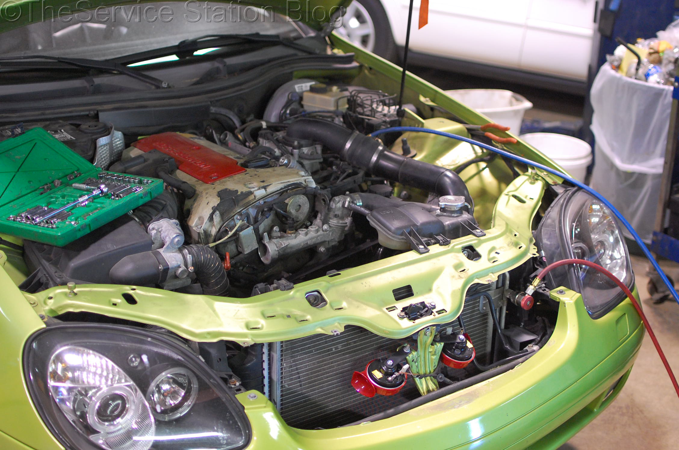
Bonus: I also did an A/C Evac and Recharge on this Merc and had to actually remove the grille to access the high side service port! Crazy German engineering….
 * All photos were shot with a Nikon D40 and a 35mm 1.8 lens. If you have a Nikon DSLR, you owe it to yourself to get one of these lenses!
